Understanding 11-Pin Relays
What is an 11-Pin Relay?
An 11-pin relay is an electromagnetic switch used in industrial control systems․ Its versatility stems from its 3C/O configuration, offering three commons and outputs․ These relays facilitate efficient, reliable circuit control․
What is an 11-Pin Relay?
An 11-pin relay is a type of electromagnetic relay commonly utilized within industrial control systems․ Distinguished by its 11 pins, it offers versatile control and connection capabilities․ These relays are often referred to as 3C/O relays, signifying three commons and outputs, enabling them to manage up to six circuits efficiently and reliably․ Their widespread popularity is attributed to their compatibility with a broad spectrum of applications․
These relays adhere to industry-standard wiring and pin arrangements, facilitating seamless replacements for comparable relays without necessitating modifications to wiring or hardware․ Whether employed in automotive systems, industrial equipment, or diverse electrical systems, a solid grasp of 11-pin relays ensures accurate and secure installations․ The 11-pin configuration provides a robust solution for complex control requirements, rendering it indispensable in various applications․
Common Applications of 11-Pin Relays
11-Pin relays find extensive use across numerous industrial control systems owing to their versatility and dependable performance․ These relays are commonly employed in automation processes, providing precise control over various devices and machinery․ Their ability to manage multiple circuits simultaneously makes them ideal for complex control scenarios, such as those found in manufacturing plants and processing facilities․
Moreover, 11-pin relays are frequently integrated into motor control circuits, enabling efficient starting, stopping, and protection of electric motors․ In HVAC systems, they regulate temperature and airflow by controlling fans, dampers, and compressors․ Security systems also benefit from 11-pin relays, which facilitate reliable switching and interlocking functions․ Their robust construction ensures longevity and consistent operation, rendering them indispensable in critical applications requiring dependable control․

11-Pin Relay Wiring Diagram Basics
An 11 pin relay wiring diagram shows how to connect components in a circuit․ Each pin has a specific function, working together to achieve the desired electrical effect safely and correctly․
Components of an 11-Pin Relay Diagram
An 11-pin relay diagram comprises several key elements essential for understanding its function․ These diagrams typically feature colored lines, each representing a specific wire or electrical connection, guiding the user in proper wiring procedures․ Symbols denote the various components, like the coil, contacts (normally open and normally closed), and power source․
Understanding these symbols is critical for interpreting the diagram correctly․ Pin numbers are clearly marked, indicating where each wire should be connected on the relay socket․ A legend or key is often included to explain the meaning of each symbol and color code, providing further clarity․
The diagram also illustrates the internal connections within the relay, showing how the coil energizes to switch the contacts․ This helps in visualizing the relay’s operation and troubleshooting potential issues․ Accurate diagrams are invaluable for ensuring proper and safe wiring of the relay․
Pin Arrangement and Functionality
The 11 pins of an 11-pin relay are arranged in a specific configuration, each serving a distinct purpose in the circuit’s operation․ Typically, these pins include coil connections (for energizing the relay), common terminals, normally open (NO) contacts, and normally closed (NC) contacts․ The arrangement follows industry standards, making replacements straightforward․
The coil pins receive the voltage that activates the relay, causing the internal switch to change state․ Common terminals act as the central point, connecting to either the NO or NC contacts depending on the relay’s state․ NO contacts complete the circuit when the relay is energized, while NC contacts do so when it’s de-energized․
Understanding this arrangement is essential for proper wiring and ensuring the relay functions as intended, providing reliable control in diverse applications․

Importance of Correct Wiring
Correct wiring of an 11-pin relay is paramount for its proper and safe operation within any electrical system․ Incorrect wiring can lead to a multitude of issues, ranging from the relay failing to function at all, to causing damage to connected equipment, or even creating hazardous situations such as electrical shocks or fires․
A miswired relay might not switch circuits correctly, leading to operational failures․ It could also cause short circuits, potentially damaging the relay itself or other components in the system․ Furthermore, incorrect wiring can compromise safety, putting individuals at risk of electrical hazards․
Therefore, meticulous attention to detail and adherence to wiring diagrams are essential when working with 11-pin relays․ Verifying connections and understanding the pinout configuration are crucial steps to ensure both functionality and safety․

Types of 11-Pin Relay Diagrams
PLA type 11-pin relay diagrams illustrate wiring for control and connection․ These diagrams showcase pinouts, circuits, and wiring, crucial for understanding the electromagnetic relay’s function in electrical circuits․
PLA Type 11-Pin Relay Diagrams
PLA (Plug-in Latching) type 11-pin relay diagrams are essential for understanding the connections and control aspects of these relays․ These diagrams typically represent an electromagnetic relay with 11 pins, each serving a specific control or connection purpose․ They are commonly used in industrial control systems due to their adaptability and compatibility with various applications․
These diagrams illustrate the pinout, circuit, and wiring configurations, providing a visual representation of how the relay functions within an electrical circuit․ Understanding these diagrams is crucial for anyone working with PLA type 11-pin relays, as they ensure correct wiring and functionality․ The 11 pins facilitate control and connection, making them ideal for diverse industrial applications․
The diagrams help in identifying each pin’s function, aiding in proper installation and troubleshooting․ They are essential for both beginners and experienced technicians in the field of electrical engineering․
Timer Relay Wiring Diagrams
Timer relay wiring diagrams are essential for correctly connecting and utilizing timer relays․ These diagrams provide a visual representation of how different components are interconnected within a timer relay system․ They illustrate the proper placement and connection of wires and terminals, ensuring the timer relay functions as intended․
Understanding these diagrams is crucial for anyone working with timer relays, as it ensures accurate wiring and prevents potential issues․ The diagrams typically show the connections for power, control signals, and output contacts․ They also include details on external potentiometers and other accessories that might be connected to the relay․
By following the wiring diagram, users can confidently install and maintain timer relays in various applications․ These diagrams are especially helpful in industrial settings where precise timing and control are critical․ They also aid in troubleshooting and diagnosing any malfunctions that may arise during operation․ These diagrams help prevent errors and ensure optimal performance․
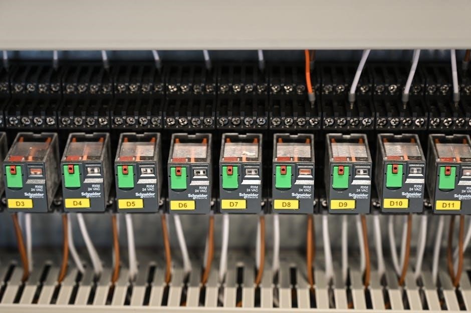
Schneider 11-Pin Relay Diagrams
Schneider 11-pin relay diagrams are essential for ensuring the proper and safe wiring of Schneider Electric’s 11-pin relays․ These diagrams offer clear instructions for connecting the relay to an electronic circuit, reducing the risk of electrical shocks and fires․ By ensuring all components are properly wired and connected, these diagrams prevent short circuits and other dangerous occurrences․
These diagrams not only make wiring easier but also provide a reference for maintenance and troubleshooting․ If something goes wrong, the diagram can help identify the issue and guide repairs․ Schneider Electric’s diagrams are designed for clarity, making them accessible to both experienced electricians and those new to relay wiring․
These diagrams typically include detailed schematics showing the pin arrangement, terminal designations, and internal connections․ They also provide information on compatible sockets and accessories․ By following these diagrams, users can ensure their Schneider 11-pin relays operate safely and efficiently․ They are a vital resource for any electrical system using Schneider relays․

Wiring Connections and Diagrams
An 11-pin relay interlocking wiring connection involves specific wiring to achieve interlocking functionality․ This configuration prevents simultaneous operation of connected devices, enhancing safety and control in industrial applications․

Interlocking Wiring Connection
In industrial automation, the 11-pin relay interlocking wiring connection is a crucial technique that ensures operational safety and prevents conflicting actions․ This wiring method uses multiple relays to create a system where the activation of one relay disables or prevents the activation of another․ This is particularly useful in scenarios where simultaneous operation of certain devices could lead to damage, inefficiency, or hazardous conditions․
The interlocking wiring connection is achieved by strategically connecting the normally closed (NC) contacts of one relay to the coil circuit of another․ When the first relay is energized, its NC contact opens, interrupting the power supply to the second relay’s coil․ This prevents the second relay from being activated while the first is in operation․ The applications of interlocking wiring are diverse, ranging from preventing motor conflicts in conveyor systems to ensuring safe operation in complex machinery․ Proper implementation requires a clear understanding of the relay’s pinout and the specific requirements of the system being controlled․
Relay Holding Circuit Diagram
A relay holding circuit, also known as a latching circuit, is a self-sustaining circuit that keeps a relay energized even after the initial trigger signal is removed․ This is achieved by using the relay’s own contacts to maintain the current flow through its coil․ The relay holding circuit diagram illustrates how the relay’s normally open (NO) contact is wired in parallel with the triggering switch․
When the switch is momentarily closed, the relay energizes, and its NO contact closes․ This closed contact then provides an alternative path for the current to flow through the relay’s coil, even after the switch is released․ The relay remains energized until the circuit is interrupted, typically by a separate reset switch that breaks the current flow to the coil․ Holding circuits are commonly used in motor control, safety interlocks, and memory functions in industrial automation systems․ Understanding the relay holding circuit diagram is essential for designing and troubleshooting these types of circuits․
Socket Wiring Diagrams
Socket wiring diagrams are essential for properly connecting an 11-pin relay to its corresponding socket․ These diagrams provide a visual representation of the pin arrangement and their respective functions, ensuring that the relay is wired correctly․ The socket wiring diagram typically includes the pin numbers, the corresponding terminals on the socket, and the wiring connections required for different applications․
These diagrams are crucial because incorrect wiring can lead to malfunctioning circuits, equipment damage, or even safety hazards․ Different types of sockets may have slightly different pin configurations, so it’s essential to refer to the correct socket wiring diagram for the specific relay and socket being used․
Furthermore, socket wiring diagrams often indicate the voltage and current ratings for each pin, which is crucial for ensuring that the wiring is adequate for the intended application․ By carefully following the socket wiring diagram, technicians and engineers can ensure a safe and reliable connection between the 11-pin relay and the rest of the electrical system․
Practical Wiring Steps
Begin by thoroughly examining the 11-pin timer relay’s wiring diagram․ This visual guide provides a comprehensive understanding of component connections, ensuring accurate wiring and proper functionality throughout the process․
Reading the Wiring Diagram
Before initiating any wiring, dedicate time to thoroughly understand the provided wiring diagram․ This diagram is your roadmap, illustrating how each component interconnects within the 11-pin relay system․ Familiarize yourself with the symbols and notations used, as they represent specific terminals, wires, and connections․
Pay close attention to the pin numbers and their corresponding functions․ The diagram will clearly indicate which pins are for power input, control signals, and output connections․ Trace the lines to see how the circuit is completed and how the relay will function when energized․
Understanding the diagram ensures you connect the wires correctly, preventing potential damage to the relay or the connected devices․ A clear comprehension of the diagram is paramount for a successful and safe wiring process, minimizing errors and maximizing the relay’s operational efficiency within the intended application․
Preparing the Wires
Proper wire preparation is crucial for establishing secure and reliable connections in your 11-pin relay system․ Begin by carefully selecting wires of the appropriate gauge for the current they will carry․ Using the correct wire size prevents overheating and potential fire hazards․
Next, use wire strippers to carefully remove a small section of insulation from the ends of each wire․ Ensure you strip enough insulation to allow for a secure connection to the relay and socket terminals, but avoid exposing excessive bare wire, which could lead to short circuits․
If the wires are stranded, gently twist the exposed strands together to create a solid, compact end․ This makes it easier to insert the wire into the terminal and ensures a better electrical connection․ Clean, properly prepared wires are essential for a safe and functional 11-pin relay setup․
Connecting the Wires to the Relay and Socket
With your wires prepared, carefully connect them to the corresponding terminals on both the relay and the socket․ Refer to the wiring diagram to ensure each wire is placed in the correct location․ A precise connection is vital for proper functionality and safety․
When inserting the wires, make sure they are fully seated in the terminals․ Tighten the terminal screws securely to clamp the wires in place, but avoid over-tightening, which could damage the terminals or the wires themselves․ A firm, secure connection guarantees reliable electrical contact․
After connecting each wire, gently tug on it to confirm it is properly secured․ This simple step can prevent loose connections, which could cause intermittent operation or even system failure․ Double-check all connections against the wiring diagram before proceeding․

Safety Considerations
Wiring diagrams reduce electrical hazards․ Proper wiring and connections prevent dangerous short circuits․ The Schneider diagram ensures components are correctly connected․ This prevents electrical shocks and the potential for fire hazards․
Reducing Risk of Electrical Shocks and Fires
When working with 11-pin relays, safety is paramount to prevent electrical shocks and fires․ Utilizing a detailed wiring diagram, such as the Schneider 11 Pin Relay Diagram, helps ensure all components are connected correctly, minimizing the risk of short circuits․ These diagrams provide clear instructions for proper wiring, which is essential for preventing dangerous occurrences․
Improper wiring can lead to significant hazards, including electrical shocks for those handling the equipment and the potential for fires if circuits are overloaded or shorted․ A reliable wiring diagram acts as a crucial reference, guiding users to establish secure and stable connections․
Regularly inspect connections to ensure they remain tight and undamaged․ Following safety protocols and using the correct tools are also vital steps․ By adhering to these guidelines, you can significantly reduce the risk of electrical accidents and ensure a safer working environment․
Ensuring Proper Connections
Ensuring proper connections is crucial when working with 11-pin relays to maintain system reliability and prevent hazards․ Begin by carefully examining the wiring diagram, such as the Omron 11-Pin Relay Wiring Diagram, to understand the correct pin assignments and wiring paths; Verify that each wire is connected to the designated terminal, paying close attention to polarity and voltage requirements․
Use appropriate tools for stripping and crimping wires to ensure secure and reliable connections․ Avoid loose or frayed wires, as these can cause intermittent failures or short circuits; After making each connection, gently tug on the wire to confirm it is firmly attached to the terminal․
Double-check all connections against the wiring diagram before applying power to the relay․ Properly labeled wires can also help prevent confusion during installation and maintenance․ Regularly inspect the connections for signs of corrosion or damage, and promptly address any issues to ensure long-term reliability and safe operation․

Resources and Further Learning
To expand your knowledge, explore wiring diagram PDFs for various 11-pin relays․ Online forums offer discussions and insights from experienced users․ These resources enhance understanding and practical application skills․
Wiring Diagram PDFs
Wiring diagram PDFs are indispensable resources when working with 11-pin relays, offering clear and concise visual representations of the connections required for proper operation․ These PDFs typically illustrate the pin arrangement, internal circuitry, and external connections needed to integrate the relay into a circuit․ High-quality PDFs provide detailed labeling and color-coding, simplifying the wiring process and reducing the likelihood of errors․

Furthermore, wiring diagram PDFs often include specific information about the relay’s electrical characteristics, such as voltage and current ratings, ensuring compatibility with the intended application․ They serve as a valuable reference for both novice and experienced electricians, facilitating accurate and safe wiring practices․ Accessing these diagrams is crucial for successful relay implementation․
Online Forums and Discussions
Online forums and discussions are invaluable resources for anyone working with 11-pin relays and their wiring diagrams․ These platforms provide a space for individuals to share knowledge, ask questions, and troubleshoot issues related to relay wiring․ Experienced electricians, engineers, and hobbyists often participate in these forums, offering guidance and practical advice based on their own experiences․
Users can find solutions to common wiring challenges, clarify ambiguities in wiring diagrams, and learn about best practices for relay installation․ Furthermore, online discussions often feature real-world examples and case studies, providing context and deeper understanding of relay applications․ Engaging in these communities fosters collaborative learning and accelerates problem-solving in electrical projects․